Why UML Modeling?
We build models to communicate the desired structure and behavior of our system.
Build A Dog House? If you want to build a kennel, prepare wood, nails, and some basic tools (such as a hammer, saw, and tape measure), and you're ready to go. From making a small preliminary plan to completing a properly functioning kennel, it may be possible to go a few hours without the help of anyone else. As long as the kennel is big enough and does not leak too much, the dog can live and work happily. Rework is always possible if it doesn't work as expected, which is nothing more than making the dog feel aggrieved.
If you want to build a house for your family, you can start working with wood, nails and some basic tools, but it takes a long time, and families must need more of the house than dogs do for kennels. In this case, unless you've built a house many times before, you'll need to make some detailed plans in advance to start building before you succeed. At least some sketches should be drawn to show what the house looks like.
 If you want to build a qualified house that meets the needs of the family and conforms to local building codes, you need to draw some architectural drawings so that you can think about the actual details of the use of the room and lighting, heating and plumbing. Once these plans have been developed, a reasonable estimate of the time and material required for this work can be made. While it is possible to build such a house yourself, it would be much more efficient if others worked together and subcontracted many key parts of the project or purchased prefabricated materials. As long as they follow the plan, no more than the time and budget, the family is likely to be satisfied with the new house. The new house will not be completely satisfactory without a plan. Therefore, it is best to plan and carefully handle changes as early as possible.
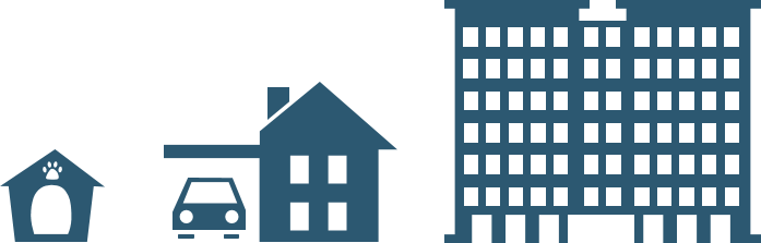
If you're building a high-rise office building, it's foolish to have wood, nails, and some basic tools ready before you start working. Because the money you use may belong to someone else, they will ask for the size, shape, and style of the building. At the same time, they often change their minds, even after the project begins. Because the cost of failure is too high, a detailed plan must be made. The person in charge of architectural design and construction is a huge organization, and you are only part of it. The organization will need a variety of design drawings and models to communicate with each other. As long as you have the right people and tools and actively manage the process of transforming building concepts into real buildings, the building will meet the requirements for use. If you want to continue with your construction work, you must strike a balance between using requirements and actual construction techniques, and handle the rest of the construction team members, neither putting them at risk nor overworking them.
What is a Model?
So, what is a model?
Simply put:
A models is a simplification of reality that attempts to capture the 'essence' of the phenomenon with the minimum level of complexity
The model provides a blueprint for the system. The model can include a detailed plan, or a master plan that considers the system from a high level. A good model includes the main elements that have a wide impact, while ignoring the minor elements that are independent of the given level of abstraction. Each system can be described by different models in different aspects, so each model is a semantically closed system abstraction. Models can be structured, emphasizing the organization of the system. It can also be behavioral, emphasizing the dynamic aspects of the system. Why the model? A basic reason is that modeling is to better understand the system being developed.
Four objectives were achieved through modeling:
- Models help visualize the system based on the actual situation or the required style.
- The model can regulate the structure or behavior of the system.
- The model provides a template for the construction of the system.
- The model records the decisions made.
The History of UML
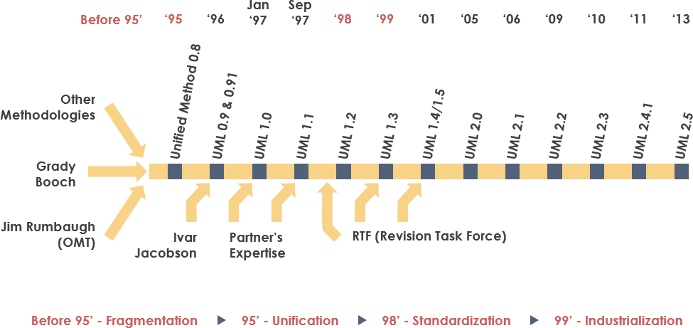
In January 1997, IBM, ObjecTime, Platinum Technology, Ptech, Taskon, Reich Technologies, and Sofiteam also submitted RFP responses to OMG. These companies joined UML partners to contribute their ideas, and together they produced a revised UML 1.1 response. The focus of UML 1.1 is to improve the clarity of UML 1.0 semantics and incorporate contributions from new partners. It was submitted to OMG for their consideration and adopted in the fall of 1997.1 and enhanced by 1.1 to 1.5, followed by UML 2.1 from 01 to 06 (the current version of UML is 2.5)
UML function
Main functions of UML include:
Unified standards
Object orientation. UML is a modeling language supporting object - oriented software development.
Visualization and strong performance
Process-independent, UML is not dependent on a specific software development process.
Clear concept, concise modeling representation, clear graph structure, easy to master and use.
Views in UML
Views in UML include Use Case View, Logical View, Implementation View, Process View, Deployment View, etc. These five views are called " 4+1” view. As shown in the figure below:
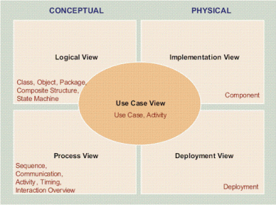
Logical view. The logical view focuses on functions, including not only the functions visible to users, but also the "auxiliary function modules" that must be provided to realize user functions. They could be logical layers, functional modules, and so on.
Development perspective. The development view focuses on packages, including not only the source programs to be written, but also third-party SDKS and off-the-shelf frameworks and libraries that can be used directly, as well as the system software or middleware on which the developed system will run. There may be some kind of mapping between the development view and the logical view: for example, the logical layer often maps to multiple packages.
Process the view. The processing view focuses on runtime concepts such as processes, threads, and objects, as well as related concurrency, synchronization, and communication issues. Dealing with the relationship between views and development views: The development view typically focuses on the static dependencies of compile-time packages that will appear as objects, threads, and processes when run. The processing view is more concerned with the interaction of these runtime units. The problem.
Physical view. The physical view focuses on how "the target program and its dependent runtime libraries and system software" are ultimately installed or deployed on physical machines, and how machines and networks are deployed to meet the reliability and scalability requirements of the software system. The relation between physical view and processing view: the processing view pays special attention to the dynamic execution of the target program, while the physical view pays special attention to the static position of the target program. The physical view is an architectural view that comprehensively considers the interaction between the software system and the overall IT system.
Four basic principles of modeling
First, choosing which model to create has a profound impact on how to solve problems and form solutions.
Second, each model can be represented at a different level of precision.
Third, the best models are linked to reality.
Fourth, a single model or view is not enough. It is best to use a set of almost independent models to approximate each important system from multiple angles.
Things are in UML
There are four things in UML:
(1) Structural things
(2) Behavioral things
(3) Grouping things
(4) Annotation things
Structural things: describe conceptual or physical elements. Structural things are collectively called classifiers.
Type
Interface.
Collaboration: An interaction is defined. It is a group composed of a group of roles and other elements that work together to provide a certain collaborative behavior. These collaborative behaviors are greater than the sum of the individual behaviors of all elements.
Use cases
Active class: its object has at least one process or thread, so it can control the activity.
Component: The modular component of the design system design will be realized after hiding a set of external interfaces.
Product: It is a physical and replaceable component in the system, which includes physical information, such as source code files, executable programs, and scripts.
Node: The physical element at runtime, which represents a computer resource, usually at least some memory and processing capabilities.
The above elements are the basic structural things that can be included in the UML model. They also accept variants, such as participants, signals, applications, processes, threads, applications, documents, files, libraries, pages, and tables.
Behavioral things. Interaction, and State Machine.
Grouping things: Package: Unlike components, it is purely conceptual.
Annotation things: remarks, note, comments and description
Relationship in UML
There are 4 relationships in UML:
(1) Dependence
(2) Association
(3) Generalization
(4) Realization
Recommended UML Readings
- Unified Modeling Language (UML)
- What is UML?
- Why UML Modeling?
- Overview of the 14 UML Diagram Types
- What is Class Diagram?
- What is Component Diagram?
- What is Deployment Diagram?
- What is Object Diagram?
- What is Package Diagram?
- What is Composite Structure Diagram?
- What is Profile Diagram?
- What is Use Case Diagram?
- What is Activity Diagram?
- What is State Machine Diagram?
- What is Sequence Diagram?
- What is Communication Diagram?
- What is Interaction Overview Diagram?
- What is Timing Diagram
- What is UML Collaboration Diagram?
- UML Association vs Aggregation vs Composition
- UML Class Diagram Tutorial
- How to Model Constraints in UML?
- State Machine Diagram vs Activity Diagram
- How to Identify Actors?
- Types of Actor in Use Case Model
- What is Model-View and Control?
- How to Model MVC Framework with UML Sequence Diagram?
- UML - Behavioral Diagram vs Structural Diagram
- What is UML Extensibility Mechanism?
- UML Practical Guide - All you need to know about UML modeling
- UML Modeling, Software Process and Tool
- UML - Modeling Software Architecture with Packages
- All You Need to Know about State Diagrams